Pile Schematics, Notations and Abbreviations
Pile Schematics
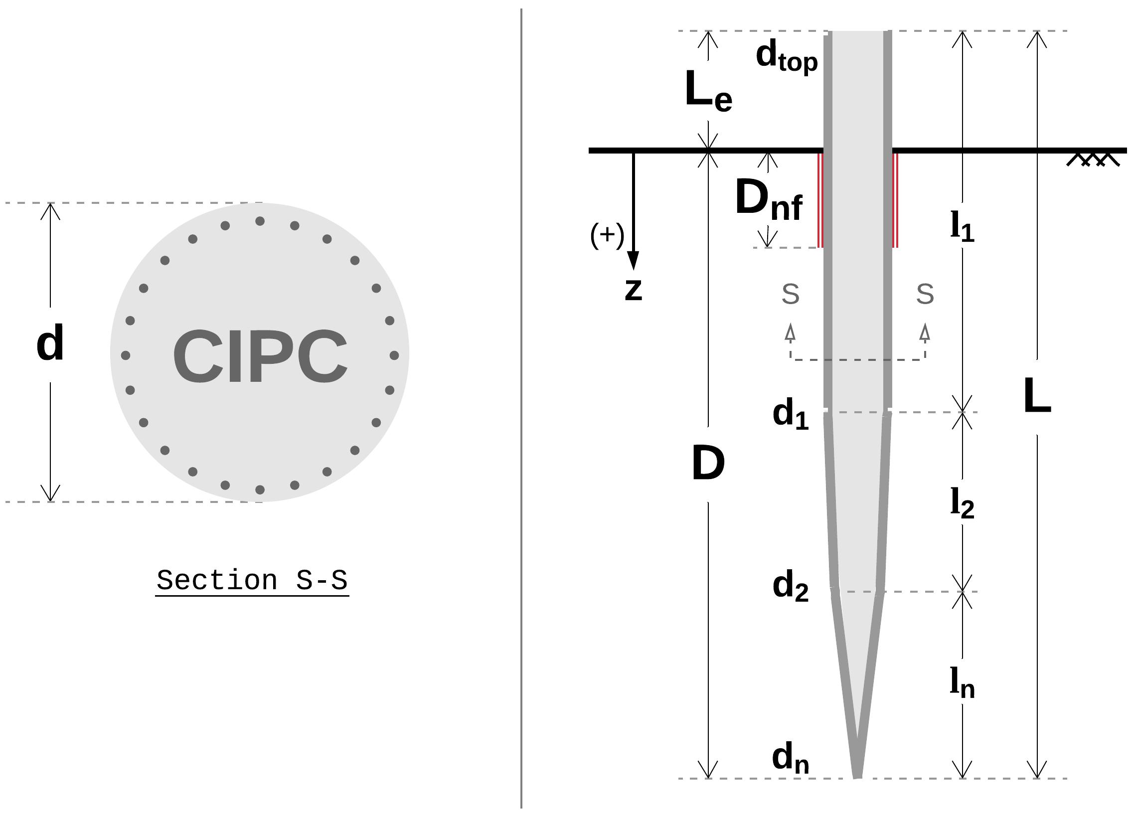
Consolidating the various data sources presented the challenge of referring to the same pile features with different names and symbols. In an effort to standardize and facilitate analytical processes, the following schematics were produced showing all relevant symbols.
Steel H-Piles
Schematic shown in Fig. 3. Section details for english H-Piles are provided in Table 7.
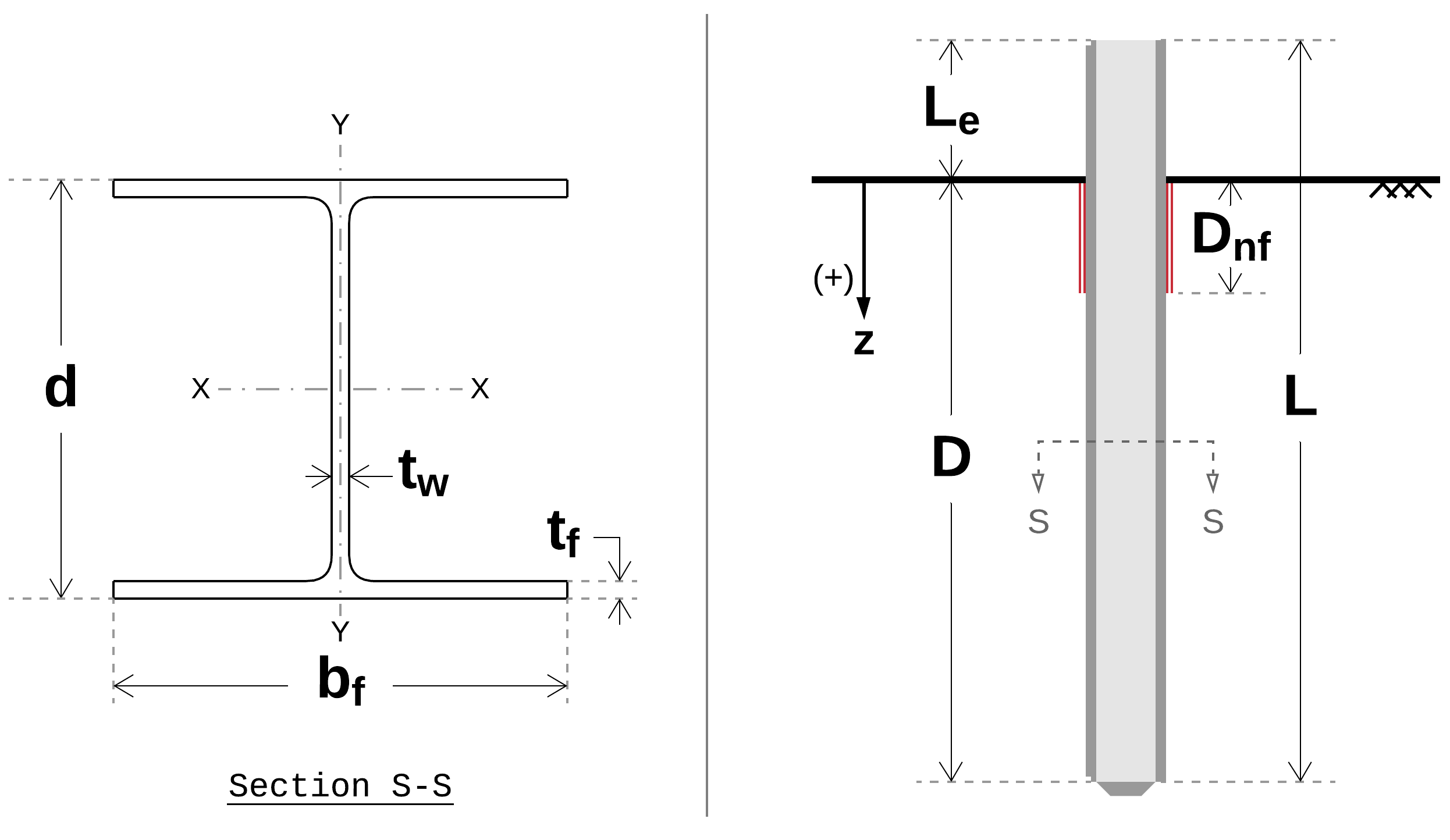
Fig. 3 Appendix: H-Pile Schematic
Section |
Area |
Perimeter |
Depth |
Web Thickness |
Width |
Box Area |
Box Perimeter |
|---|---|---|---|---|---|---|---|
A |
P |
d |
tw |
bf |
Ab |
Pb |
|
in2 |
in |
in |
in |
in |
in2 |
in |
|
HP14x117 |
34.4 |
86.35 |
14.21 |
0.805 |
14.885 |
211.5 |
58.19 |
HP14x102 |
30 |
85.75 |
14.01 |
0.705 |
14.785 |
207.1 |
57.59 |
HP14x89 |
26.1 |
85.21 |
13.83 |
0.615 |
14.695 |
203.2 |
57.05 |
HP14x73 |
21.4 |
84.55 |
13.61 |
0.505 |
14.585 |
198.5 |
56.39 |
HP12x84 |
24.6 |
72.37 |
12.28 |
0.685 |
12.295 |
151.0 |
49.15 |
HP12x74 |
21.8 |
71.91 |
12.13 |
0.605 |
12.215 |
148.2 |
48.69 |
HP12x63 |
18.4 |
71.35 |
11.94 |
0.515 |
12.125 |
144.8 |
48.13 |
HP12x53 |
15.5 |
70.87 |
11.78 |
0.435 |
12.045 |
141.9 |
47.65 |
HP10x57 |
16.8 |
59.75 |
9.99 |
0.565 |
10.225 |
102.1 |
40.43 |
HP10x42 |
12.4 |
58.87 |
9.7 |
0.415 |
10.075 |
97.73 |
39.55 |
HP8x36 |
10.6 |
47.77 |
8.02 |
0.445 |
8.155 |
65.40 |
32.35 |
Pipe Piles (Open and Closed Ended)
Schematic shown in Fig. 4.
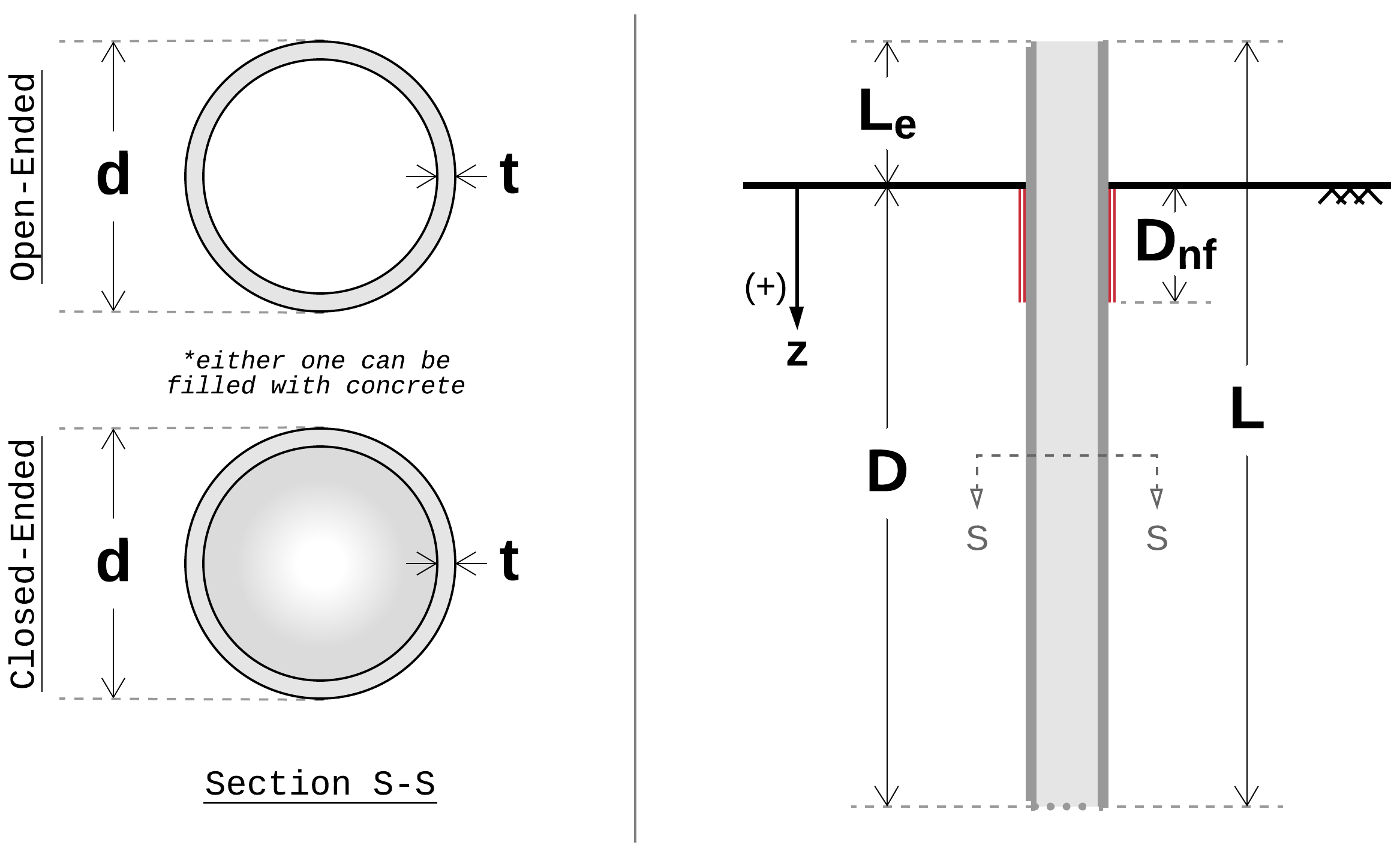
Fig. 4 Appendix: Pipe Pile Schematic
Notations and Abbreviations
Various notation styles are encountered across literature. This document uses symbols adopted from Hannigan et al., 2016a and Fellenius, 1999. Fig. 8 presents a quick reference to the most commonly used symbols. See below for the complete list.
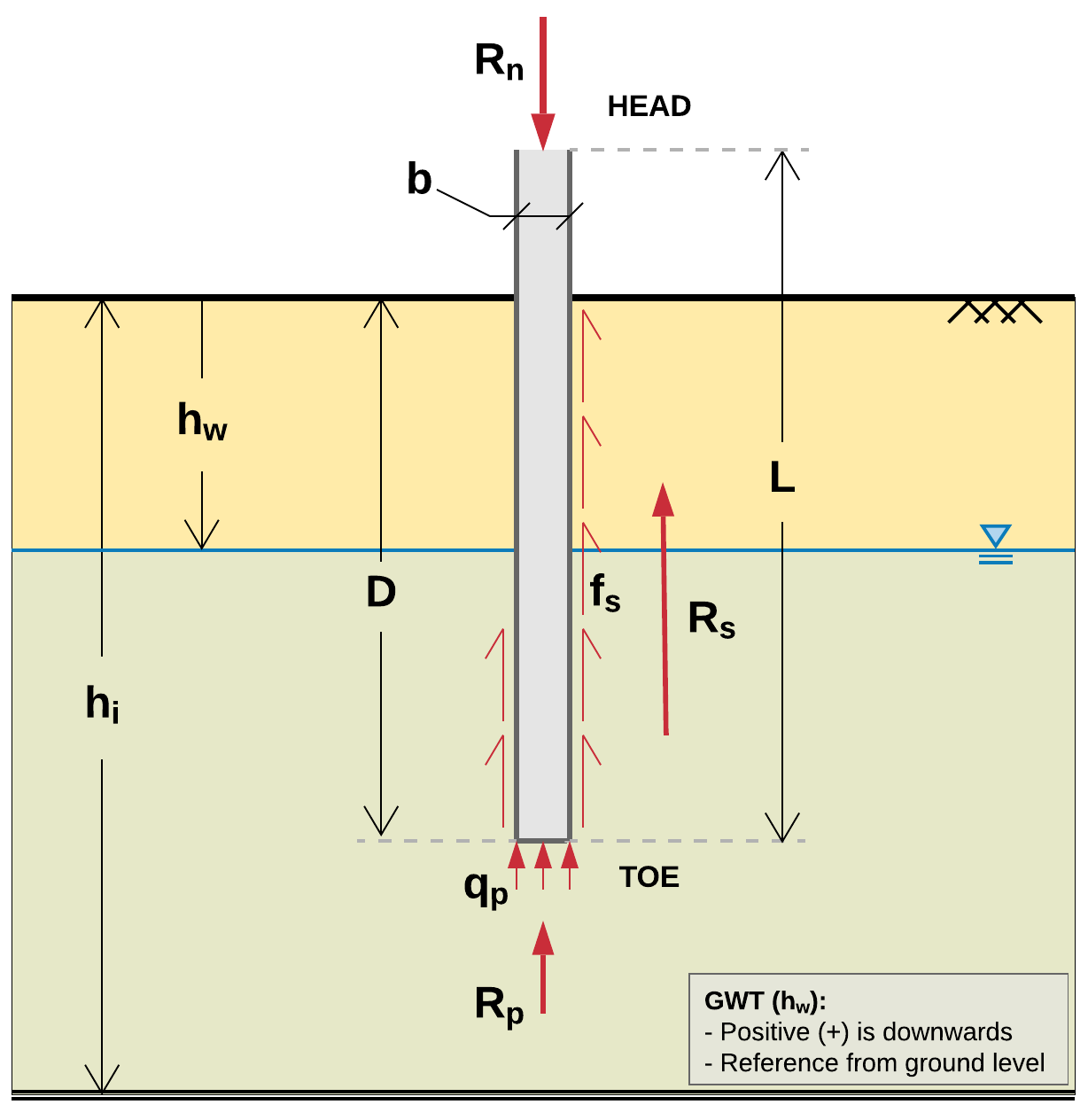
Fig. 8 Appendix: Typical profile view with embedded pile and associated symbols
- \(h_w\)
Depth to groundwater table (feet/meters)
- \(h_i\)
Soil layer height (feet/meters)
- \(b\)
Pile diameter/side (inches/centimeters)
- \(L\)
Pile length, total (feet/meters)
- \(D\)
Pile length, embedded (feet/meters)
- \(A\)
Pile cross sectional area (sq.in/sq.cm)
- \(A_p\)
Pile cross sectional area, toe (sq.in/sq.cm)
- \(A_{pp}\)
Pile cross sectional area, plugged (sq.in/sq.cm)
- \(A_s\)
Pile shaft surface area (sq.ft/sq.m)
- \(A_{si}\)
Pile shaft surface area, interior (sq.ft/sq.m)
- \(A_{so}\)
Pile shaft surface area, exterior (sq.ft/sq.m)
- \(R_n\)
Nominal resistance, total (tons/MN)
- \(R_s\)
Nominal shaft resistance (tons/MN)
- \(R_p\)
Nominal toe resistance (tons/MN)
- \(f_s\)
Unit shaft resistance, adhesion (…)
- \(f_{si}\)
Unit shaft resistance, interior (…)
- \(f_{so}\)
Unit shaft resistance, exterior (…)
- \(q_p\)
Unit toe resistance (…)
- \(N\)
Uncorrected field SPT resistance value
- \(N_1\)
SPT N value corrected for overburden stress
- \(N_{60}\)
SPT N value corrected for 60% energy transfer
- \((N_1)_{60}\)
SPT N value corrected for energy and overburden stress
- \(Q_c\)
Pile calculated load (capacity), often referred to as nominal resistance, \(R_n\) (tons/MN)
- \(Q_m\)
Pile measured (aka interpreted) capacity as obtained from static load tests (tons/MN)
- \(Q_p\)
Pile predicted capacity obtained from statistical and predictive models (tons/MN)
- \(E\)
Elastic modulus of material, Young’s modulus (…)